GBAmp3 Mod PCB Order Now
also available at retromodding.comand Deadpan Robot

Saturday, December 18, 2010

Litmer: finished device

I took pictures of finished working device. I have removed 12v regulator from circuit because my main power changed from 14.4V power adapter to 12V lead-acid battery. So I don't need this regulator anymore. 5V regulator is still there.
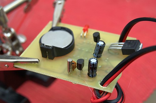
Then you can see 2 capacitors near crystal, they are compensation capacitors for that crystal. DS1302 rtc clock is designed for 6pf load crystals, but I have only 12pf load crystal, that's why I place another 6pf of capacitors in parallel with crystal.
There is a led indicating when lights are on or off without pwm.

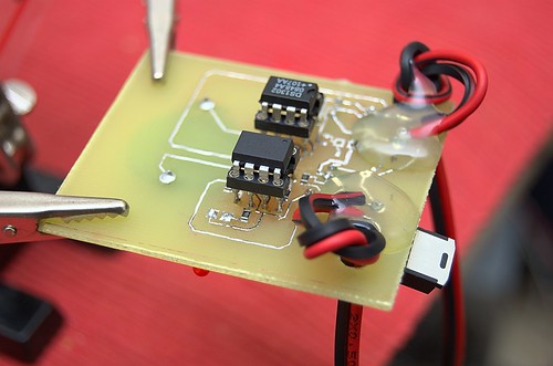
I have printed this pcb mirrored that's why I placed attiny25 and ds1302 on copper side of pcb along with smd resistors :)

Firmware code is available in my repository: code.avrnoob.com/litmer
Compilled firmware size is 2046 bytes and attiny25 have 2048 bytes of flash, so I have 2 spare bytes for some futures to add :) Actually there are still some bugs, but there are no place to fix them. Some bugs already fixed in repository.

And here are the pictures:

Litmer project pcb

Litmer project pcb

Friday, December 17, 2010

Litmer: PCB design

The project is already done actualy. The Litmer timer works now in my chicken coop controlling lights inside coop, emulating sunrise and sunset with pwm. This is how pcb design looks like. It's pretty big pcb. The biggest part is lithium backup battery with holder.
DS1302 or lithium backup battery fail while temperature is under -10C or so. While Litmer is on main power nothing fail.

Saturday, December 4, 2010

Litmer: lights pwm and time compare

Finished yesterday with software PWM driver to slowly turn lights on and off. Time compare changed in watchdog inteerupt. Now if current time is betweend on and off then on state forced. It's usfull for example if I have to reset avr or after powerdown or after burning time correction into eeprom etc. PWM is working on Timer0 interrupt.
Can not test this code in emulator because it have many bugs with timers and watchdog. But my test led works fine. So I hope it'll work with transistor and power mosfet.

Friday, December 3, 2010

Litmer: 8 seconds watchdog with power-down sleep mode

Played with power-down sleep mode. It's very low power consumption mode, cpu is not running. Then played with watchdog timer. Set it to 8 seconds with prescaler and enabled interrupt. So every 8 seconds watchdog wakeups cpu and run interrupt. In this interrupt code I going to check rtc time and compare it with on/off times stored in eeprom and then take action.
I will probably make a battery backup for this device, so it can run on AC when available or on battery and charge battery when on AC. So lower power consumption is better. Take a look at code at:code.avrnoob.com/litmer.

Litmer: DS1302 driver works

Just tested my code with DS1302 chip. EEPROM have init byte, if it set to 0x01 then mcu will write time to rtc chip and then set this byte to 0. Next bytes is init hour and minutes values.
Output from chips is correct and time is moving:

This output hour as 00011001 in BCD format = 19 decimal and minutes as 00000011 = 3. So the time is 19:03.

Litmer: DS1302 driver output test

This is how the test program output looks like:


Note signle spike on LED channel, it is for separation between time init and actual time read. I have not connected rtc chip, so there are all zeroes while reading time. Additional spikes on LED channels is just led turning on and off indicating end of program.
Overall output looks right, next is to test with actual DS1302 rtc chip.

Litmer: DS1302 driver done

Done with DS1302 driver. Read/Write hours/minutes/seconds functions with bcd format conversion. Take a look at the test code (not tested with actual rtc chip yet):


Take a look at the driver code in repository: code.avrnoob.com/litmer/src it is ds1302.c

Litmer: 3 wire complete

Just added a write_byte function and some minor fixes to other functions. This is the test code:


And this is how the output looks like:


Channel 1 is SCLK pin, channel 2 is RST pin, channel 3 is IO pin.

Thursday, December 2, 2010

Litmer: 3 wire rtc communication

Just wrote some function for ds1302 rtc 3 wire communication interface. They are setup, init, start/stop and read byte. Next is write byte and then I can start on actual rtc functions, like set time/hour/minute, get time etc.


You can check out code in my repository: code.avrnoob.com/litmer.

Wednesday, December 1, 2010

Litmer: read eeprom and dev environment

So I call this project a Litmer.

Just done with my dev environment, it's Makefile, some scripts for read/write fuses, read/write eeprom, program script. I'm using avrdude programmer in Ubuntu 10.10.

I've set clock with fuses to 8MHz without CKDIV8 bit. And I've set EESAVE bit for preserving EEPROM erase while burning new firmware with avrdude.

Eeprom.bytes is default EEPROM bytes (128), which I will be using for time/timer setup for rtc.

Not much done for today.

All code revisions saved with Mercurial distributed revision control tool on bitbucket.org hosting.
Take a look at the code at code.avrnoob.com/litmer.

I wrote a test program which checks if first EEPROM byte is set to 0x01 and turn on led on PB0 if it is.